Elektromanyetik, 100 1.Öğretim, Grup440, arduino
Introduction— about the project
Hello makers this time I am sharing my new project of Robotic Arm using ArduinoUNO board and Micro 180 degree servo motors I hope you’ll find it interesting.
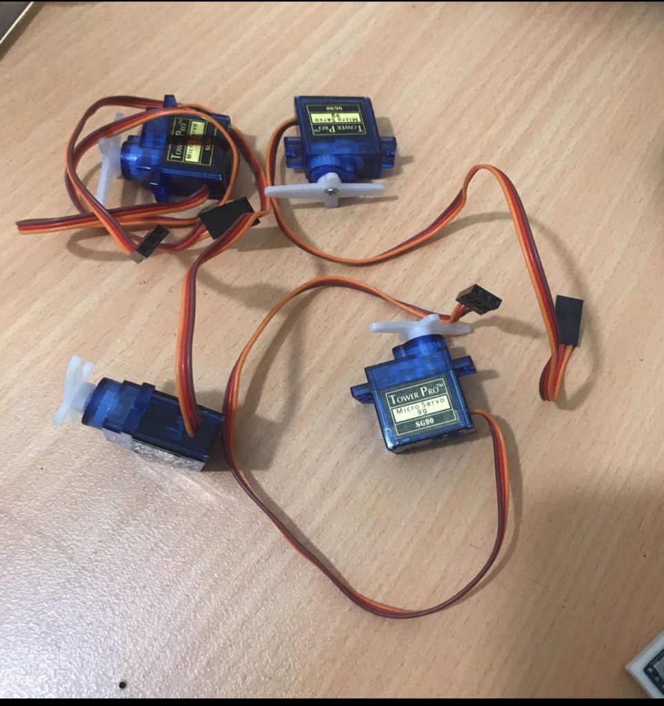
I will try to show you how you can control 4nos. Tower Pro 9g servo arranged as a robotic arm, you’ll have 4 DOF, can control this Robotic arm with 4 set of potentiometer arranged parallel with our robotic arm, Robotic arm will move, act & follow potentiometer movement, you can pick and place tiny items with the help of tiny griper attached at the end of the arm.
Some IMP Points
Some IMP points before processed.
1) There is always shaking problem with small servos, so use onboard 5V & GND for potentiometer and keep delay time in programming code as small as possible 5mili sec recommended.
2) Must use external 5V DC source for servo to avoid extra load on Arduino board.
3) Must short onboard GND & External DC source GND.
4) Potentiometer Range advisable to keep between 1K to 22K OHM & potentiometer must be Single turn or best if you manage to find half turn it will sink perfectly with servo 180 degree freedom of motion.
5) It is advisable not to fix any mechanical joints permanently before first trial.
6) In material list I will take notes of major items only, other supporting accessories you can use according to your convenience.
7) Use wires as thin as possible for Potentiometer wiring so potentiometers will reach there extent positions without bearing the tension of thick wires.
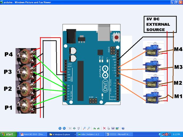
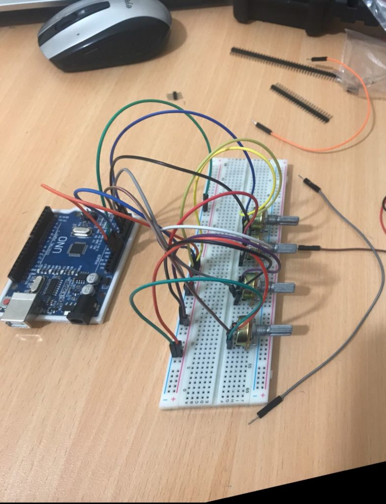
Connections:
– The external battery VCC / GND connect to the breadboard.
– The Arduino GND connect to the breadboard’s GND input
– The servo connections we use in this project are as follows;
Orange Input – Signal Input
Red Input – Power Input (VCC)
Brown Input – Ground Input(GND)
– The potentiometer connections we use in this project are as follows;
Two outer pins are power (VCC) and ground (GND)
Middle pin is signal pin
– The Servo1 VCC and GND connect to the breadboard’s VCC / GND inputs
– The Servo1 Signal connect to the Arduino Digital PWM 3
– The Servo2 VCC and GND connect to the breadboard’s VCC / GND inputs
– The Servo2 Signal connect to the Arduino Digital PWM 5
– The Servo3 VCC and GND connect to the breadboard’s VCC / GND inputs
– The Servo3 Signal connect to the Arduino Digital PWM 6
– The Servo4 VCC and GND connect to the breadboard’s VCC / GND inputs
– The Servo4 Signal connect to the Arduino Digital PWM 9
– The Potentiometer’s one outer pin connect to the breadboard or the Arduino board VCC input
– The Potentiometer’s other outer pin connect to the breadboard or the Arduino board GND input
– The Potentiometer’s middle pin connect to the Arduino Analog 1-2-3-4 input
Programming code: —–
#include
Servo myservo1;
Servo myservo2;
Servo myservo3;
Servo myservo4;
int potpin1 = 0;
int potpin2 = 1;
int potpin3 = 2;
int potpin4 = 3;
int val1;
int val2;
int val3;
int val4;
void setup()
{
myservo1.attach(6);
myservo2.attach(9);
myservo3.attach(10);
myservo4.attach(11);
Serial.begin(9600);
}
void loop() {
{
val1 = analogRead(potpin1);
val1 = map(val1, 0, 512, 0, 180);
myservo1.write(val1);
Serial.println(val1);
val2 = analogRead(potpin2);
val2 = map(val2, 0, 512, 0, 180);
myservo2.write(val2);
val3 = analogRead(potpin3);
val3 = map(val3, 0, 512, 0, 180);
myservo3.write(val3);
val4 = analogRead(potpin4);
val4 = map(val4, 0, 512, 0, 180);
myservo4.write(val4);
delay(5);
}
}
and here you are the video of all the process :
last we would like to thanks all the teachers … doctors and the teamwork …..
best regards …
thank you …..
“Robot Arm Control with a Potentiometer” üzerine bir düşünce
Great job,
From Indonesia