What is power supply ?
Power supple is the basic devices in electronic world ,and all of electronic labs have it .
Its convert from our network signal AC to DC which it used in all electronic devices like computer -mobil- tv
A variable power supply is a regulator that electricians and electrical project hobbyists use to test the capacity of voltage for any project they may have completed. The power supply is used as a gauge to make sure the piece of work the person has completed is able to withstand certain amounts of voltage and current load. Tests are generally conducted by applying different amounts of voltage to the piece of completed work a little at a time to ensure the stability of the circuit the individual has created. These types of power supplies also are used by hobbyists to power small electronics requiring variable voltage and by tattoo artists to power tattooing guns.
Aim of power supply .
A power supply is an electronic device that supplies electric energy to an electrical load . The power supply converts the ac voltage to dc voltage by many steps . There is a lot of power supply type for many value but the mostly used in the laboratories is the variable power supply because We can eliminate many devices in a single device whose value depends on the value required for use .
For our project we will use the next Components.
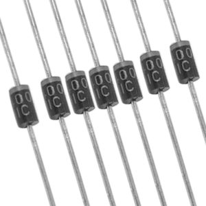
( 6 pieces of diodes ) type 1N4001
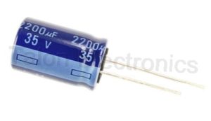
2200 micro farad Capacitor .
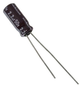
2.2 micro farad Capacitor
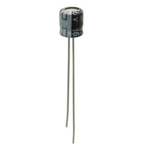
47 micro farad Capacitor .
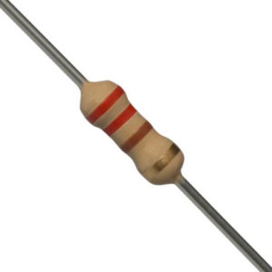
220 Ω Resistor .
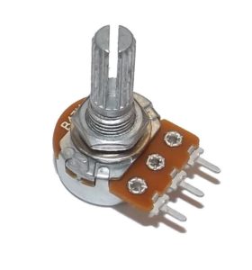
5 k Ω Variable Resistor .
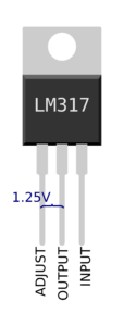
Regulator type ( LM317 )
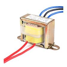
Transformer which transfer from ( 220 to 24 V ) .
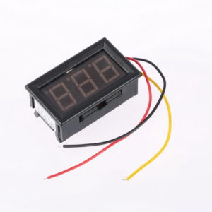
Digital Voltmeter
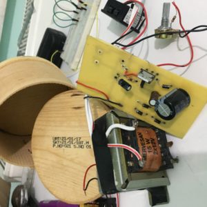
In here we have the power supply picture that we made like it .
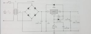
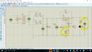
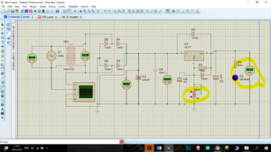
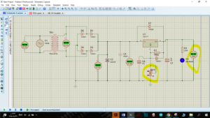
At first we draw the circuit in ( Proteus 8 Demonstration ) program .
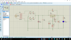
From this drawing we checked the circuit if its working or not .
Theoretical information about variable power supply :
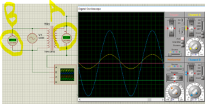
1-STEP in the photo we have alternating voltage source has value 310 Vmax (in digital oscilloscope) equal 220 Vrms (in ac voltmeter point B)and this voltage value mostly used in turkey . after transform we will get another value this value dependent on transformer her the transformer has ratio 1/9=0.11 .
so Vs=Vp*1/9=220Vrms*0.11=24.2Vrm (as we can see in ac voltmeter point A and Vsmax = Vpmax*0.11=310*0.11=34.1Vmax (as we can see in digital oscilloscope channel A).
THE FULL-WAVE RECTIFIERS:
We have two ways to type of rectifier 1-half wave rectifier 2- full wave rectifier here we used the full wave rectifier because in this way we will not lose any current and we will use the positive and negative current as we will see.
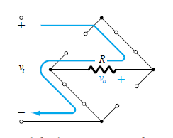
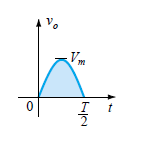
During the period T0 to T/2 the polarity of the input is as shown The resulting polarities across the ideal diodes are also shown to reveal that D2 and are conducting while D1 and D4 are in the “off” state.
And the output will be as shown
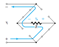
During the period T/2 to T the polarity of the input is as shown The resulting polarities across the ideal diodes are also shown to reveal that D1 and D4 are conducting while D2 and D3are in the “off” state.
And the output will be as shown
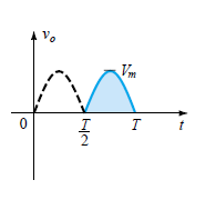
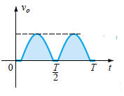
we will get to alternative voltage Only positive polarity as shown.
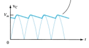
FILTERING : to get DC voltage, we must work to make no difference between Vmax and Vmin so here we will use capacitor because the capacitor has a certain voltage so that when the voltage exceeds the specified amount the capacitor starts charging and when the voltage drops below a certain amount the capacitor works as a battery so we will get voltage as shown.
Voltage Regulators: Three-terminal regulators designed for fixed output voltages require only external capacitors to complete the regulation portion of the power supply. Filtering is accomplished by a large-value capacitor between the input voltage and ground. The LM317 Voltage regulators are also available in circuit configurations that allow the user to set the output voltage to a desired regulated value. The LM317, for example, can be operated with the output voltage regulated at any setting over the range of voltage from 1.2 to 37 V. The regulator will make the Oscillator voltage and it is dependent on the variable resistor in the circuit so that V0=1.25*((R1+Rv)/R1). If we assume Rv (variable resistor) is zero so we will get V0=1.25*((R1+R2)/R1=1.25*((220+0)/220)=125V. This is the minimum value we can get
And If we assume Rv (variable resistor) 2500 so we will get V0=1.25*((R1+R2)/R1=1.25*((220+2500)/220)=15.45V.
And If we assume Rv (variable resistor) 5000 (the maximum value of our resistor) so V0=1.25*((R1+R2)/R1=1.25*((220+5000)/220)=29.6V.
After know how circuit works and drawing it on Proteus we will connect all components on breadboard .
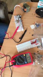
As we can show in the last figure we put all components on breadboard and the circuit works well . Now we will make printed circuit .
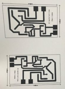
print out of our PCB layout using A4 photo paper/glossy paper
 .
.
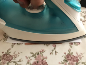
Iron It
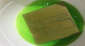
After ironing, place printed plate in Luke warm water for around 10 minutes.
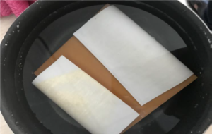
we need to be EXTREMELY careful & cautious while performing this step
1)Take a plastic box and fill it up with some water.
2) Dissolve 25ml of Hydrogen peroxide, and 50ml Hydrochloric acid (tuzruhu).
3) Dip the PCB into the Etching solution for approximately 10 mins.
4)The solution reacts with the unmasked copper and removes the unwanted copper from the PCB.
Gently move plastic box to and fro so that etching solution react with exposed copper and form iron and copper chloride.
After every 2-3 minutes check whether all copper is etched or not.
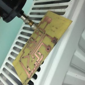
After that we get the printed circuit and we made holes for connect the components
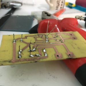
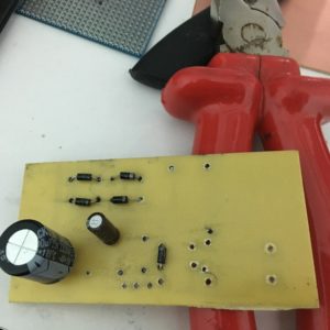
We start to connect components on printed board and soldering it on board .
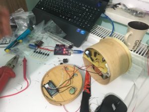
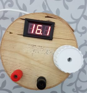
At the end we made a box for covering power supply and put the circuit in the box .